Lab 1A: Artemis Setup
Prelab
Prior to the lab session, I successfully installed the latest version of the Arduino IDE and the SparkFun Apollo3 boards manager, following the provided lab instructions.
Blink
For this task, I loaded the 01.Basics Blink example onto the board. Upon successful flashing, the onboard LED began blinking at the expected intervals.
Serial
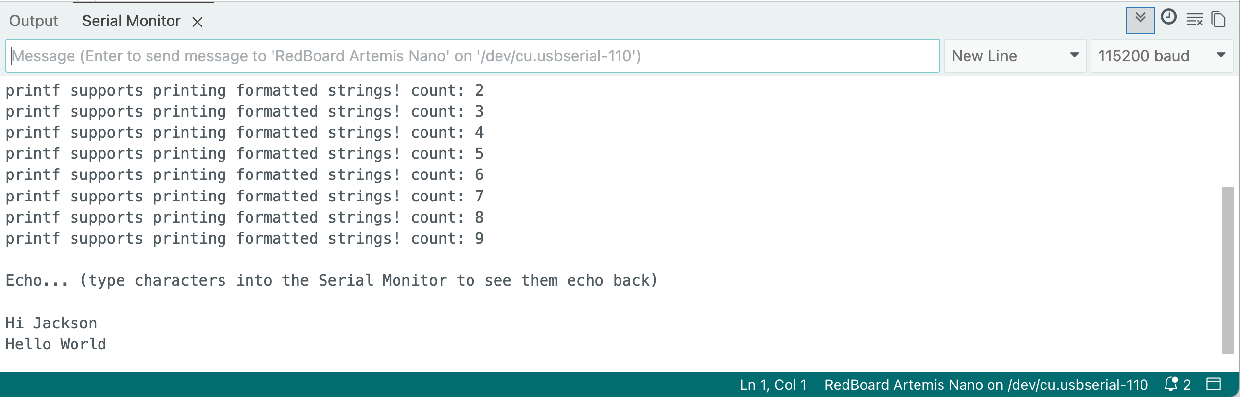
Using the Serial Monitor in the Arduino IDE, I verified that the Artemis board correctly receives character strings and echoes them back, confirming a functional serial communication link.
AnalogRead
In this experiment, I monitored the onboard temperature sensor. When I applied pressure and warmth to the sensor, the temperature readings increased significantly. This indicates that both the sensor and the analogRead function are working correctly.
MicrophoneOutput
For this part, I used an online frequency generator to produce various tones. As shown in the video, the program correctly captured the audio and displayed the corresponding frequency outputs in the Serial Monitor.
Additional Tasks for 5000-level
To implement tone detection, I defined three target frequencies: 440Hz (A4), 523Hz (C5), and 659Hz (E5). I also implemented a 10Hz tolerance window to account for signal fluctuations and environmental noise.
Using an online frequency generator, I tested the board's response to different inputs. When the board identifies a frequency within the specified range of a target note, the Serial Monitor displays a message such as: Match Note Found: E5 (663 Hz). If no match is detected, the program defaults to outputting the Loudest Freq, similar to the previous task.
Lab 1B: Bluetooth Communication
Prelab
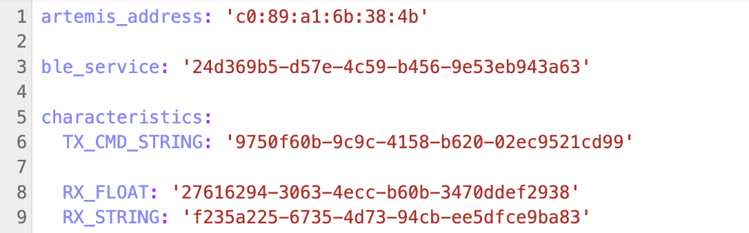
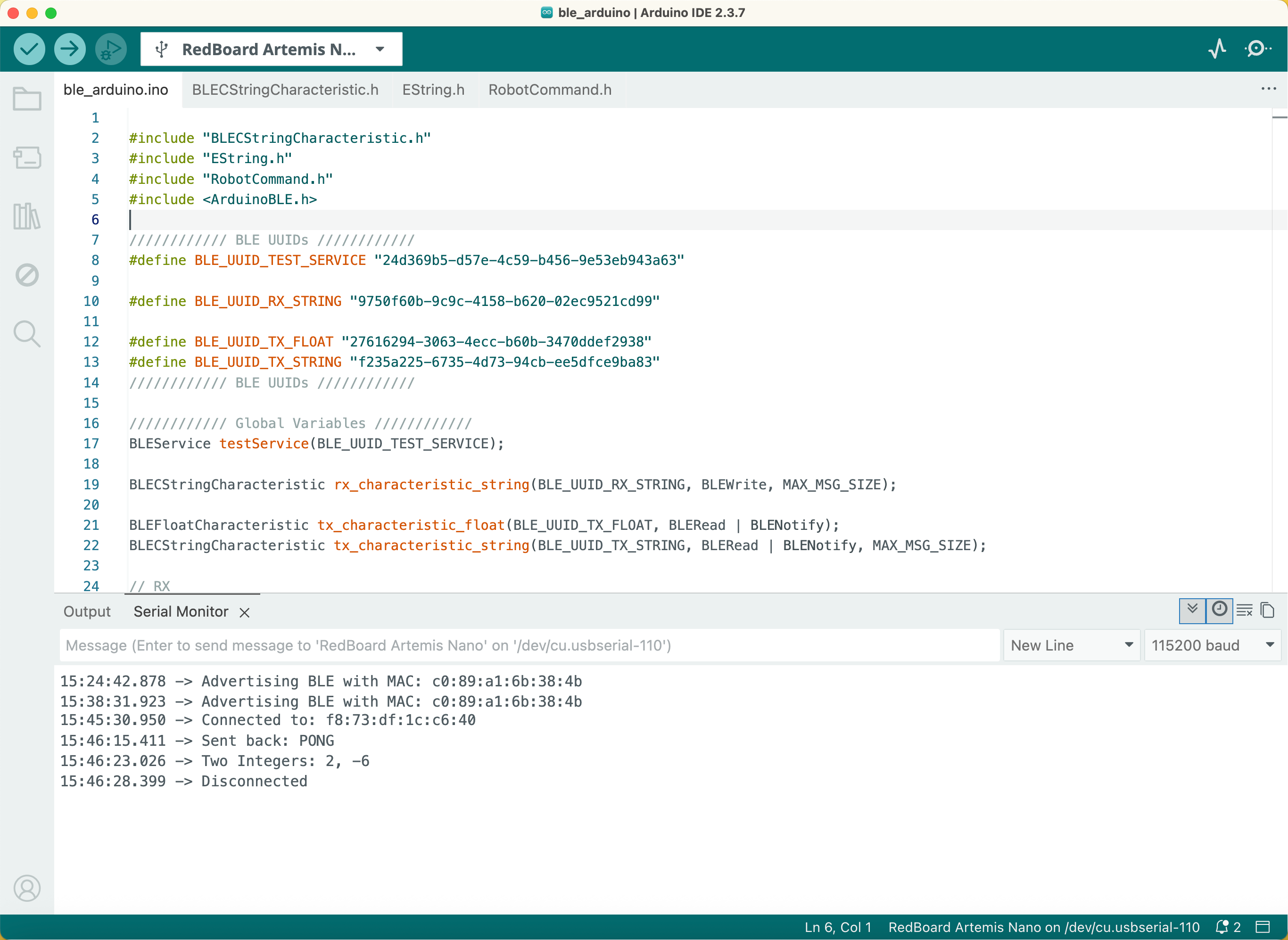
I created a Python environment named fastrobots and installed the required packages for this lab. Subsequently, I downloaded and organized the codebase into my project directory. In the Arduino IDE, I installed the ArduinoBLE library via the Library Manager. After flashing the ble_arduino.ino sketch to the board, I retrieved its unique MAC address from the Serial Monitor.
Configurations
Following the lab instructions, I updated the Python configuration files on my computer with the Artemis board's MAC address to ensure a successful connection. To verify the setup, I executed the initial Jupyter Notebook; all cells ran successfully, confirming that the computer and the board could communicate over BLE.
Task 1: ECHO
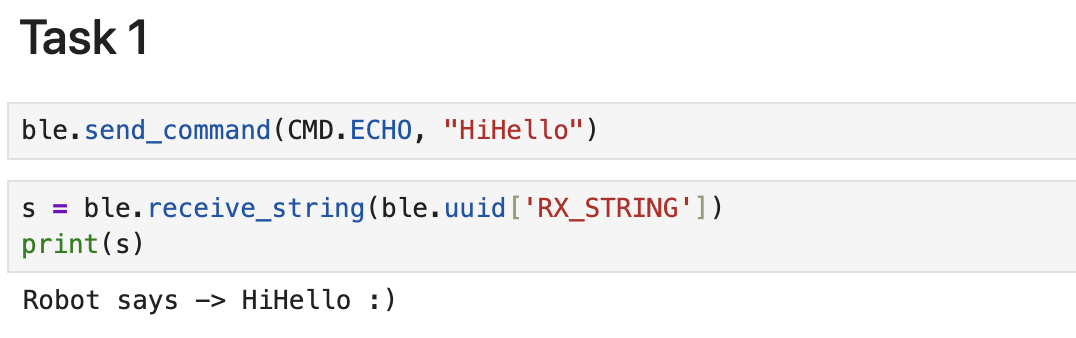
For this task, I implemented the ECHO command by adapting the logic from the existing PING function. When I sent a command containing the string "HiHello", the Artemis board successfully processed the characteristic and returned: Robot says -> HiHello :).

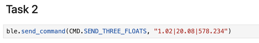
Task 2: SEND_THREE_FLOATS
I implemented the SEND_THREE_FLOATS function to extract three float values from a received command. The board parses these values and displays them in the Serial Monitor.

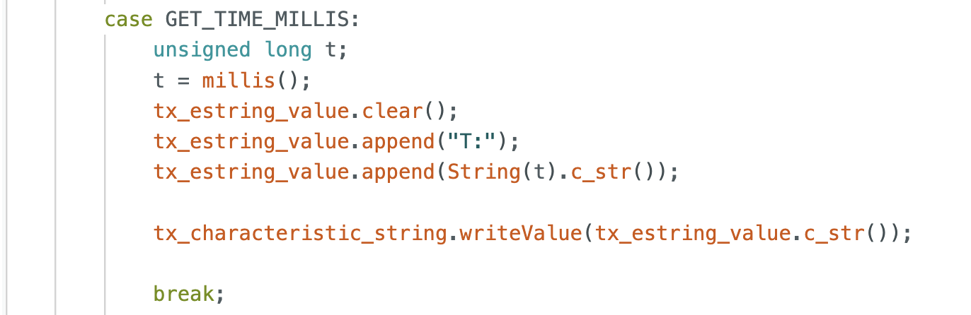
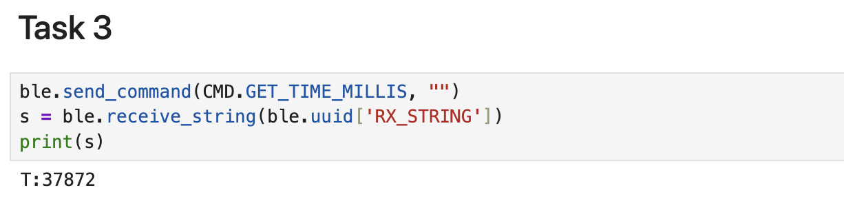
Task 3: GET_TIME_MILLIS
I implemented the GET_TIME_MILLIS command to get the board's running time in milliseconds. The command utilizes the millis() function, which returns the number of milliseconds elapsed since the program began execution. This value is then packaged and sent back to the Python client as a string.
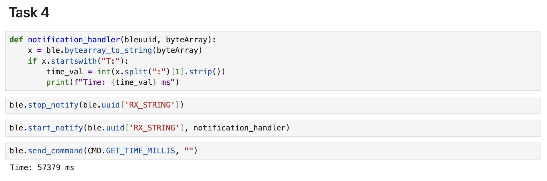
Task 4: Notification Handler
For this task, I implemented a notification_handler function. This callback function receives the raw byte array from the BLE characteristic and extracts the timestamp using string splitting and decoding. After starting notifications, I tested the loop by sending a GET_TIME_MILLIS command. The computer successfully received and printed the time value immediately upon the board's update, confirming that the notification system is working correctly for real-time data transfer.
Task 5: Loop Test
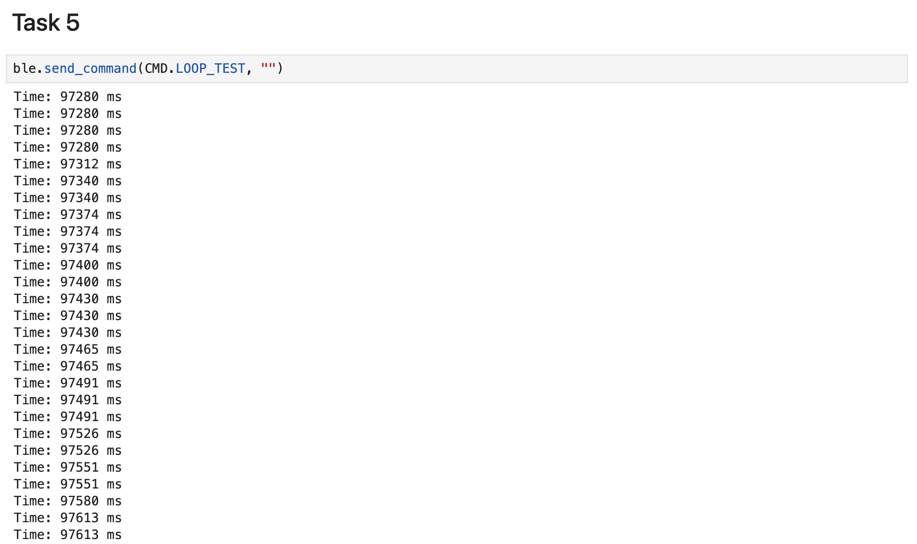
I implemented a LOOP_TEST command to measure data transfer performance over a 5000ms interval. During this loop, the Artemis board continuously updates the string characteristic with current timestamps. By monitoring the output in the Python notebook, I was able to observe the update frequency and calculate the effective data transfer rate of this communication method.
In the 5-second time interval, I received 330 messages. Therefore, the effective data transfer rate of this method is Rate = 330 entries / 5 s = 66 entries/s
Task 6: SEND_TIME_DATA
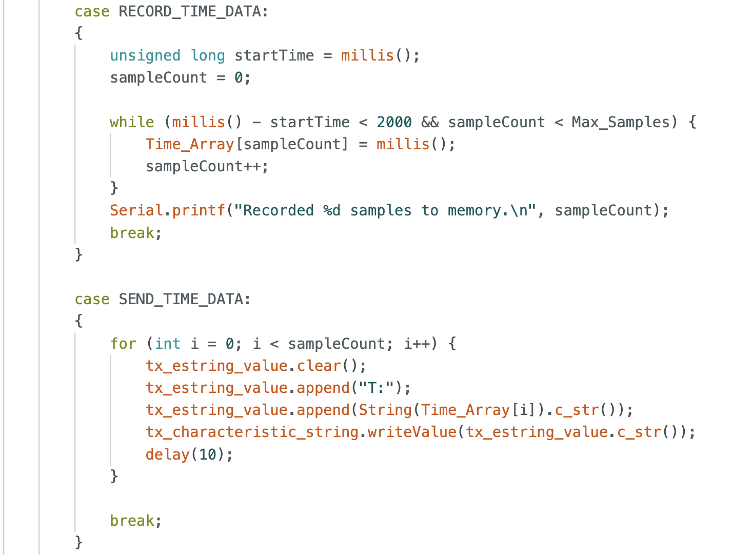
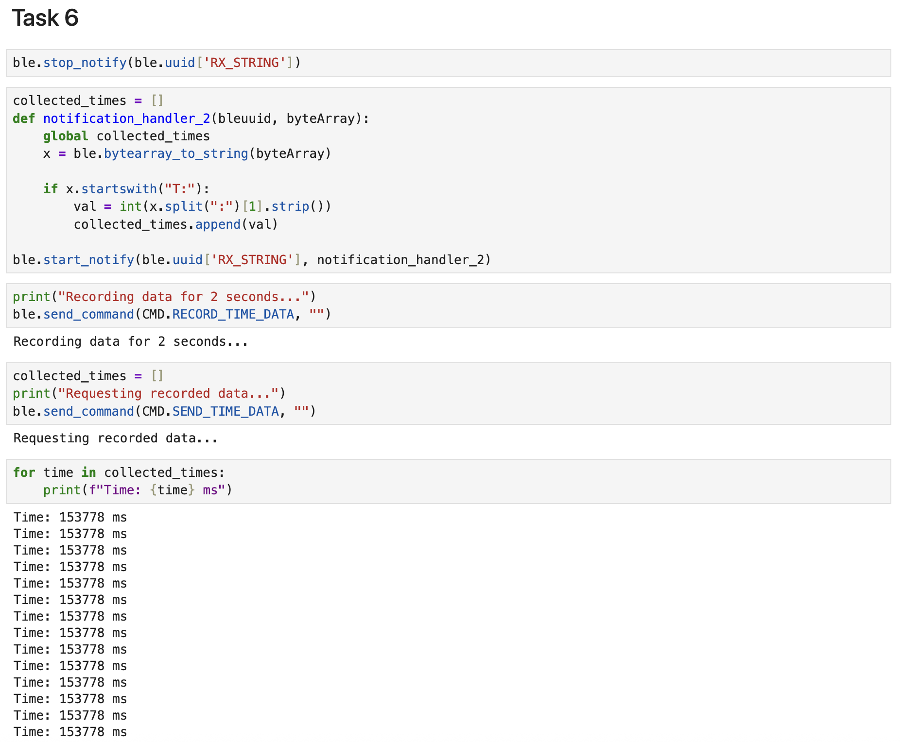
Next, I defined a global array Time_Array with a Max_Samples of 100. I wrote a RECORD_TIME_DATA function to capture and store timestamps directly into this array on the board. On the computer side, I initialized a collected_times list and implemented notification_handler_2. The handler extracts each timestamp and appends it to the Python list. Finally, I verified the data integrity by printing the collected timestamps, confirming successful data transfer from the board to the computer.
In the 100-sample set, I observed two complete timestamps and each produced approximately 30 entries. This indicates that within 1 ms, the Arduino system stored around thirty timestamp entries. Therefore, the storage rate of this method is Rate = 30 entries / 1 ms = 30,000 entries/s.
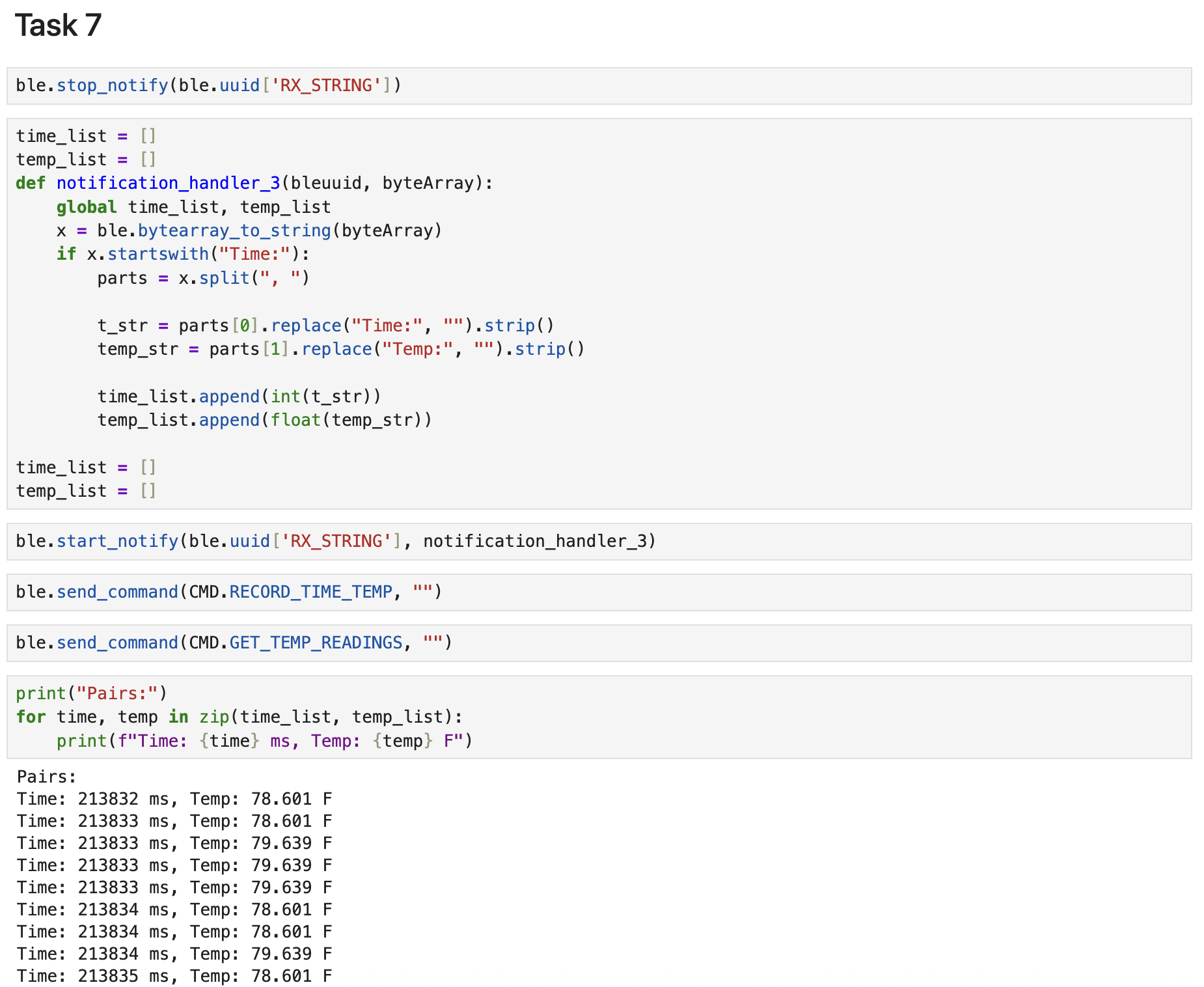
Task 7: GET_TEMP_READINGS
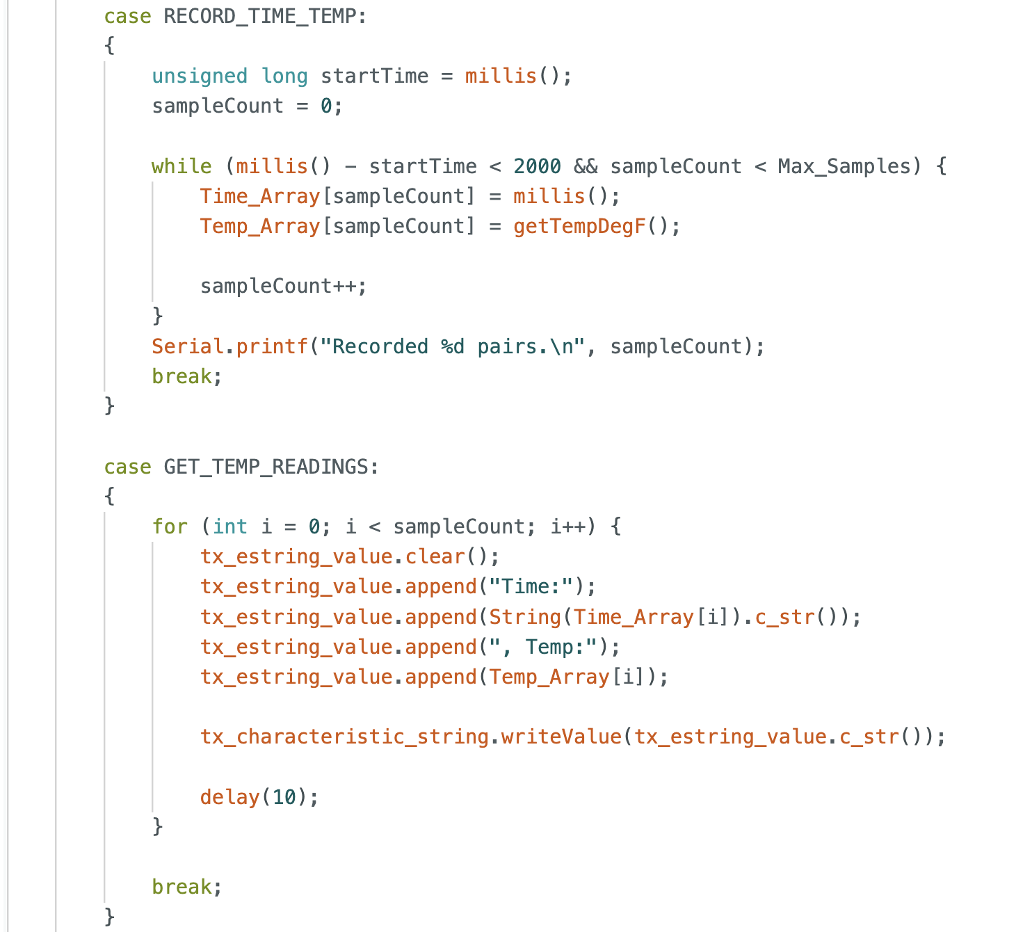
Similar to the previous task, I added a global Temp_Array to store temperature readings alongside the Time_Array. I implemented the RECORD_TIME_TEMP function to concurrently capture timestamps and their corresponding temperature values. On the computer side, I initialized time_list and temp_list and created notification_handler_3 to handle the incoming data strings. The handler extracts both values and appends them to their respective lists. Finally, I printed the results as data pairs to verify the synchronized collection of time and temperature.
Task 8: Two Methods Comparison
Method 1: Sending Data Real-Time
- Advantages: We don't need to store a large Array in board which requires less memory usage, ensuring system stability.
- Disadvantages: The transmit speed is limited by the BLE connection intervals and signal interference can lead to inconsistent sampling rates.
Method 2: Buffering Data
- Advantages: The sampling process doesn't involve low-speed Bluetooth communication, allowing for highly stable, high-frequency data capture directly into RAM.
- Disadvantages: The total amount of data that can be recorded is strictly limited by the size of the RAM, and results can only be processed after the recording period concludes.
The previous experiment demonstrated that while Method 1 transfers data at 66 entries/s, Method 2 records at 30,000 entries/s. Method 2 is significantly faster and offers superior data integrity by decoupling sampling from communication overhead.
Use Cases
- Method 1: I would choose this for live monitoring of robot status, ensuring instant access to the robot's state at any given moment.
- Method 2: I would adopt this for high-speed testing that requires complete data collection over short intervals. This ensures data integrity and allows for precise parameter backtracing during post-analysis.
Assuming we use the int data type for calculations and storage, where each int is 32 bits (4 bytes), the theoretical maximum storage capacity is calculated as follows:
$$\text{Theoretical Capacity} = \frac{384 \times 1024\ \text{bytes}}{4\ \text{bytes/int}} = 98{,}304\ \text{data entries}$$
However, in a practical application, the actual number of data entries we can store will be significantly lower than this theoretical capacity, because memory must also be reserved for system runtime and other programs rather than dedicating all RAM to data storage.
Additional Tasks for 5000-level
Effective Data Rate And Overhead
I implemented a test loop that requested reply sizes ranging from 5 to 120 bytes in 5-byte increments. For each request, the Artemis board returned a string of 'A' characters of the specified length. I recorded the round-trip time and calculated the effective data rate for each size.
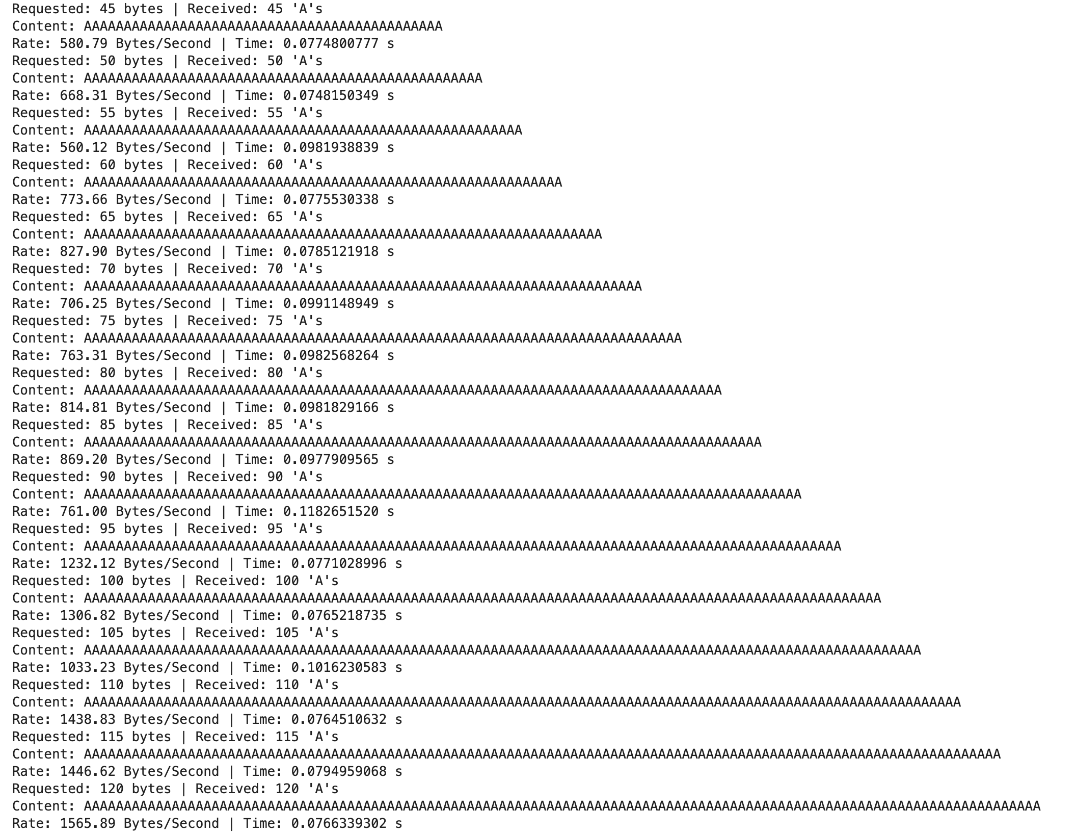
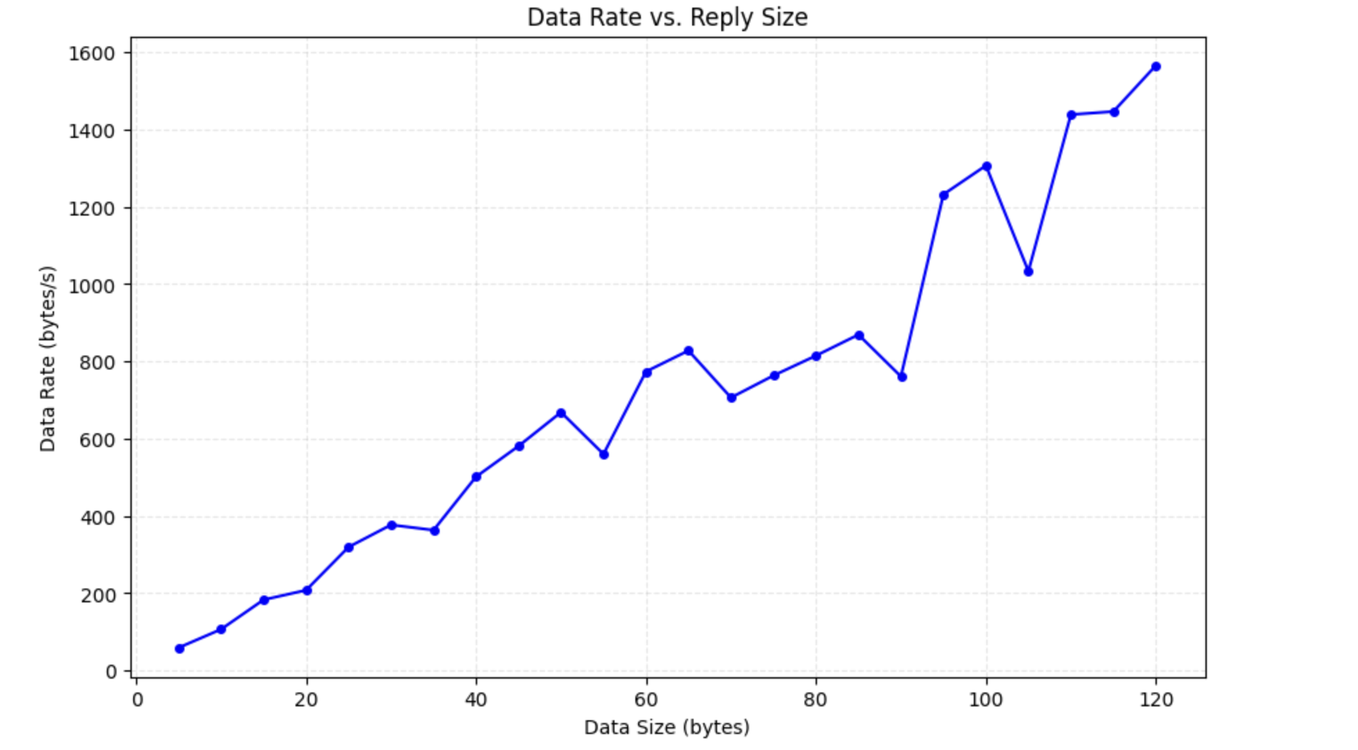
As the reply data size increases from 5 to 120 bytes, the effective data rate demonstrates a distinct upward trend, peaking at approximately 1565.89 bytes/s. This is because that, at lower payload sizes, fixed system overhead, such as BLE protocol headers and connection setup latency, constitutes a dominant portion of the total transmission time, resulting in low efficiency. Conversely, increasing the data size reduces the relative proportion of these overhead costs, allowing the system to maximize throughput within similar timeframes. Therefore, larger replies significantly optimize communication performance by reducing the effect of fixed costs. Even though the rate curve displays a "sawtooth" pattern, the overall transmission rate shows an upward trend.
Reliability
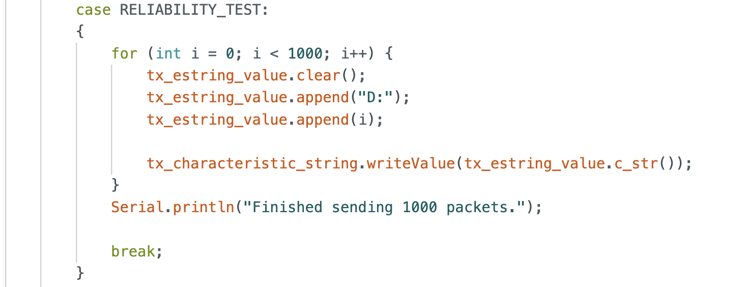
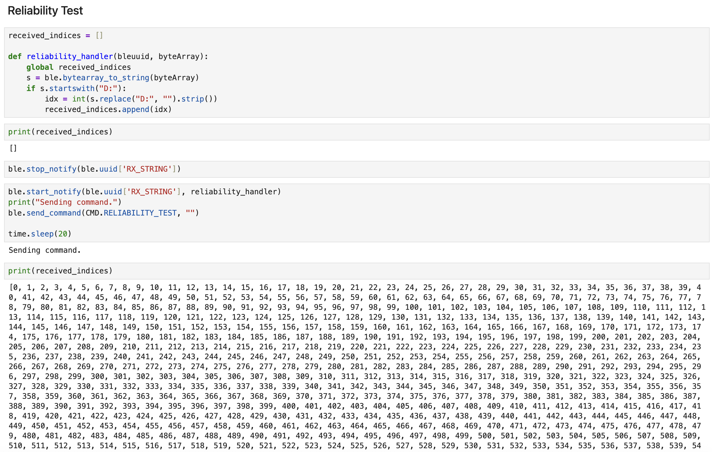
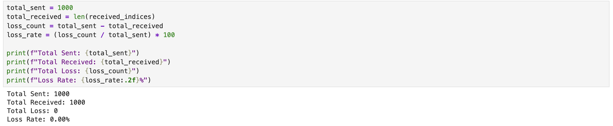
To evaluate communication reliability, I implemented a RELIABILITY_TEST function on the Artemis board that transmits a sequence of 1,000 messages formatted as "D:i" (from i = 0 to 999). On the computer, I utilized a notification handler to capture the incoming data and store it in a Python list for verification. Upon inspection, I confirmed that all 1,000 packets were collected successfully and in the correct order. This 0% loss rate demonstrates that the BLE link between the computer and the Artemis board is reliable.
Discussion
In this lab, I successfully set up the Artemis board and established Bluetooth communication with my computer. Through a series of experiments, I verified the board's basic functionalities, including blinking an LED, reading analog values, and capturing microphone input. The Bluetooth communication tests demonstrated reliable data transfer with some latency. The additional tasks for 5000-level provided insights into optimizing data transfer rates and ensuring communication reliability. Overall, this lab enhanced my understanding of embedded systems and wireless communication protocols.
Reference
Thanks to Professor Helbling and the TAs for their help during lab sessions. I refer to Katherine Hsu's website as guidance and as a reference for web design.
Note
In the report, I did not put some code implementations of simple functions and roughly duplicate parts. If necessary, please feel free to contact me.